

Which Of The Following Is True Of The Components Of An Entity-relationship Data Model?
Entity Human relationship Diagram
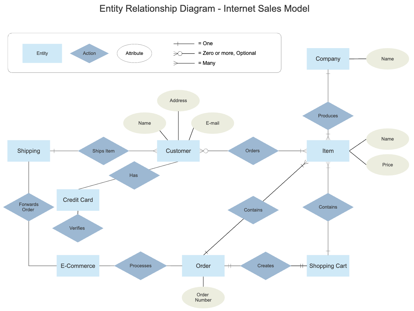
What is an Entity Relationship Diagram (ERD)?
An entity relationship diagram (ERD) shows the relationships of entity sets stored in a database. An entity in this context is an object, a component of data. An entity set is a drove of similar entities. These entities can have attributes that define its properties.
By defining the entities, their attributes, and showing the relationships betwixt them, an ER diagram illustrates the logical structure of databases.
ER diagrams are used to sketch out the design of a database.
Documenting an Existing Database Using Information
There are two reasons to create a database diagram. You're either designing a new schema or you lot need to document your existing construction.
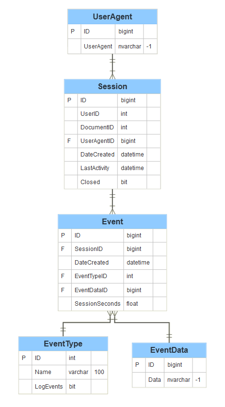
If you accept an existing database you demand to to document, y'all create a database diagram using data directly from your database. Yous can export your database structure as a CSV file (in that location are some scripts on how to this here), then have a program generate the ERD automatically.
This will be the virtually accurate potrait of your database and will crave no drawing on your part.
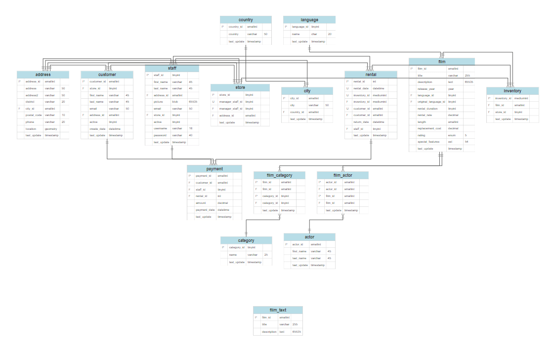
Here's an instance of a very basic database construction generated from data.
If you want to create a new programme, yous tin also edit the generated diagram and collaborate with your team on what changes to make.
Learn more about generating ER diagrams from data automatically using SmartDraw's ERD extension.
The History of Entity Relationship Diagrams
Peter Chen developed ERDs in 1976. Since then Charles Bachman and James Martin have added some slight refinements to the bones ERD principles.
Common Entity Human relationship Diagram Symbols
An ER diagram is a means of visualizing how the information a organization produces is related. In that location are five main components of an ERD:
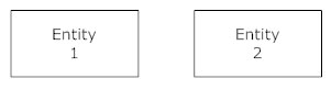
- Entities, which are represented by rectangles. An entity is an object or concept nigh which y'all desire to store information.
 A weak entity is an entity that must defined by a foreign key relationship with some other entity as it cannot exist uniquely identified by its own attributes alone.
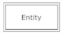
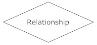
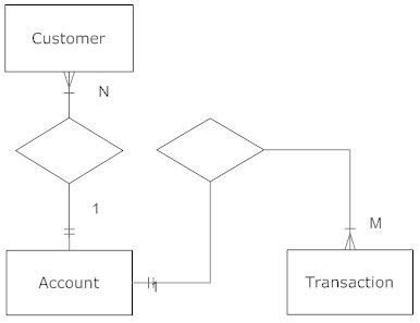
- Actions, which are represented by diamond shapes, prove how two entities share information in the database.
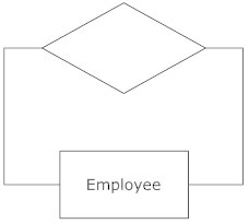
 In some cases, entities tin be cocky-linked. For example, employees tin supervise other employees.
- Attributes, which are represented by ovals. A cardinal attribute is the unique, distinguishing characteristic of the entity. For instance, an employee's social security number might exist the employee's key attribute.
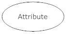 A multivalued attribute can accept more than one value. For example, an employee entity can take multiple skill values.
 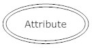 A derived aspect is based on some other attribute. For example, an employee'south monthly salary is based on the employee's annual salary.
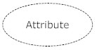
- Connecting lines, solid lines that connect attributes to show the relationships of entities in the diagram.
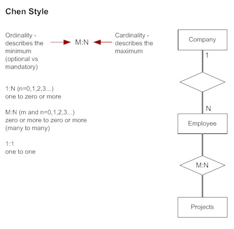
- Cardinality specifies how many instances of an entity relate to one example of another entity. Ordinality is also closely linked to cardinality. While cardinality specifies the occurrences of a relationship, ordinality describes the relationship every bit either mandatory or optional. In other words, cardinality specifies the maximum number of relationships and ordinality specifies the absolute minimum number of relationships.
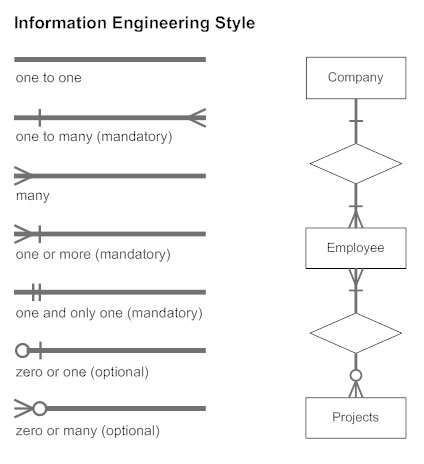
 At that place are many notation styles that limited cardinality.
Information Engineering science Manner
 Chen Way
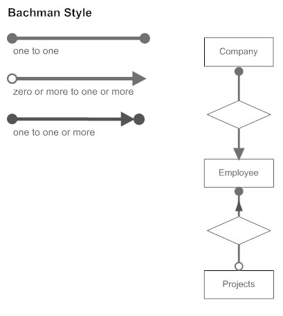
 Bachman Style
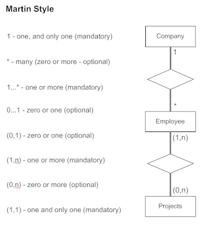
 Martin Style
ERD Explained
Watch this quick video learn more about ERD diagrams and their components.
ER Diagram Uses
When documenting a system or process, looking at the system in multiple ways increases the understanding of that arrangement. ERD diagrams are usually used in conjunction with a data flow diagram to display the contents of a data store. They help usa to visualize how data is connected in a general fashion, and are particularly useful for constructing a relational database.
Entity Relationship Diagram Tutorial
Here are some all-time practice tips for constructing an ERD:
- Place the entities. The starting time footstep in making an ERD is to place all of the entities you will use. An entity is nothing more than a rectangle with a description of something that your system stores information about. This could be a client, a managing director, an invoice, a schedule, etc. Depict a rectangle for each entity y'all can think of on your page. Keep them spaced out a flake.
- Identify relationships. Look at ii entities, are they related? If so describe a solid line connecting the ii entities.
- Depict the relationship. How are the entities related? Describe an activity diamond betwixt the 2 entities on the line yous simply added. In the diamond write a brief description of how they are related.
- Add together attributes. Whatever fundamental attributes of entities should be added using oval-shaped symbols.
- Complete the diagram. Proceed to connect the entities with lines, and calculation diamonds to describe each relationship until all relationships have been described. Each of your entities may not have whatsoever relationships, some may have multiple relationships. That is okay.
Tips for Constructive ER Diagrams
- Make certain that each entity simply appears once per diagram.
- Name every entity, relationship, and attribute on your diagram.
- Examine relationships betwixt entities closely. Are they necessary? Are there any relationships missing? Eliminate whatsoever redundant relationships. Don't connect relationships to each other.
- Apply colors to highlight important portions of your diagram.
Entity Relationship Diagram Examples
Browse SmartDraw's entire collection of ERD examples and templates

Which Of The Following Is True Of The Components Of An Entity-relationship Data Model?,
Source: https://www.smartdraw.com/entity-relationship-diagram/
Posted by: simsbutes1974.blogspot.com
0 Response to "Which Of The Following Is True Of The Components Of An Entity-relationship Data Model?"
Post a Comment